
The Science behind Sisyphus
There are several basic physics concepts that underlie Sisyphus.
Potential Energy
Potential energy is essentially stored energy. The chemical energy of a battery is potential energy and the mechanical energy of a compressed spring is potential energy. Potential energy can be converted to kinetic energy, the energy of motion, and kinetic energy can be converted to potential energy.
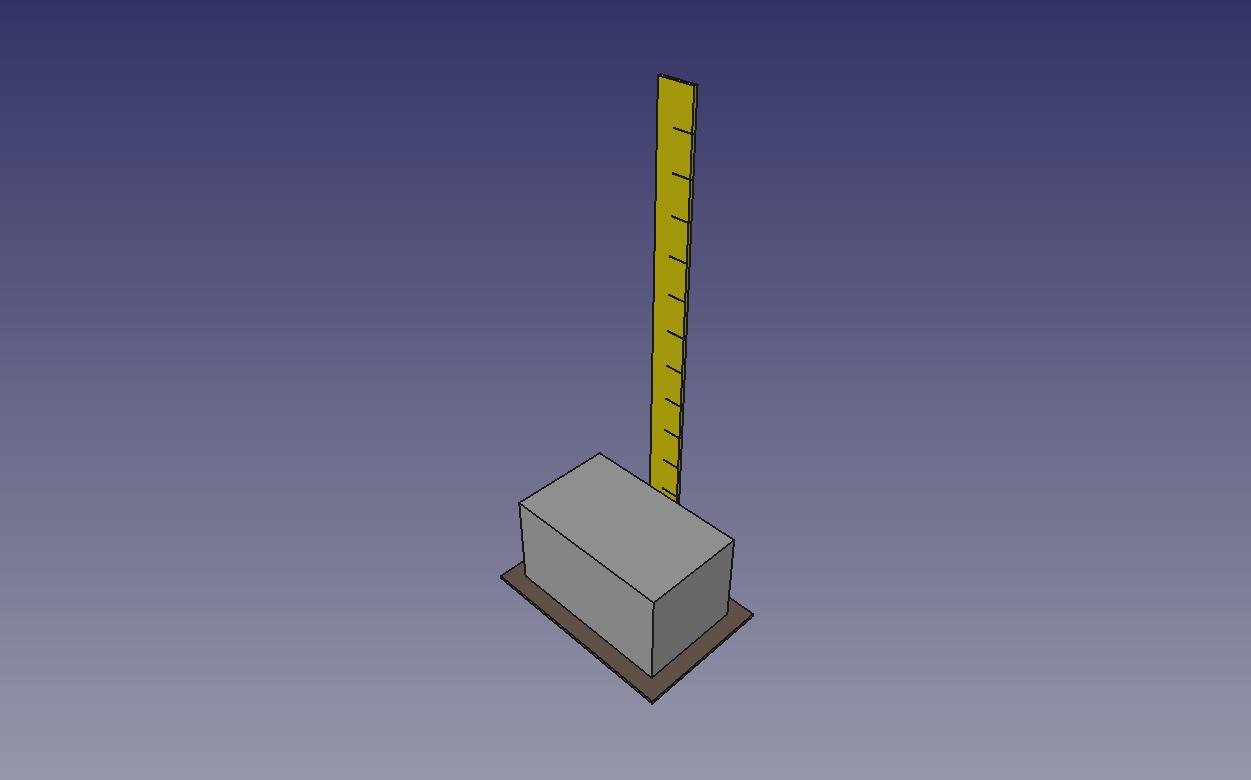
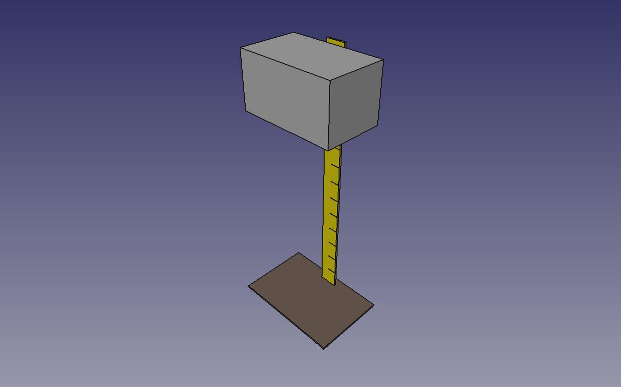
The figures below represent a 100 metric ton (220,000 pound) concrete block. Click on the left image to see it being raised 11 meters. It requires 3 kilowatt hours (KWH) to raise this block 11 meters (for a perfectly efficient lifting system). The kinetic energy of 3 KWH equals the stored (potential) energy of 3 KWH. Click on the right image to see the block being lowered. For a perfectly efficient system, 3 KWH of potential energy can be recovered as 3 KWH of kinetic energy.
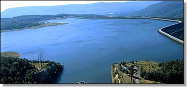
This method of storing energy is not just theoretical; it is in use around the world. One example is the Raccoon Mountain Pumped Hydro facility near Chattanooga, TN, shown below. Pumped hydro techology uses electrical energy to pump water into a lake that is high above the water source. When the stored energy is needed, the water is drained through turbines to generate electricity. About 70-75% of the electrical energy expended in pumping the water is recovered in the energy generated by the turbines. Sisyphus will use electrical energy to move concrete blocks and recover about 90-95% of the energy. Sisyphus also uses much less real estate and has much less restrictive site requirements than pumped hydro.
Magnets
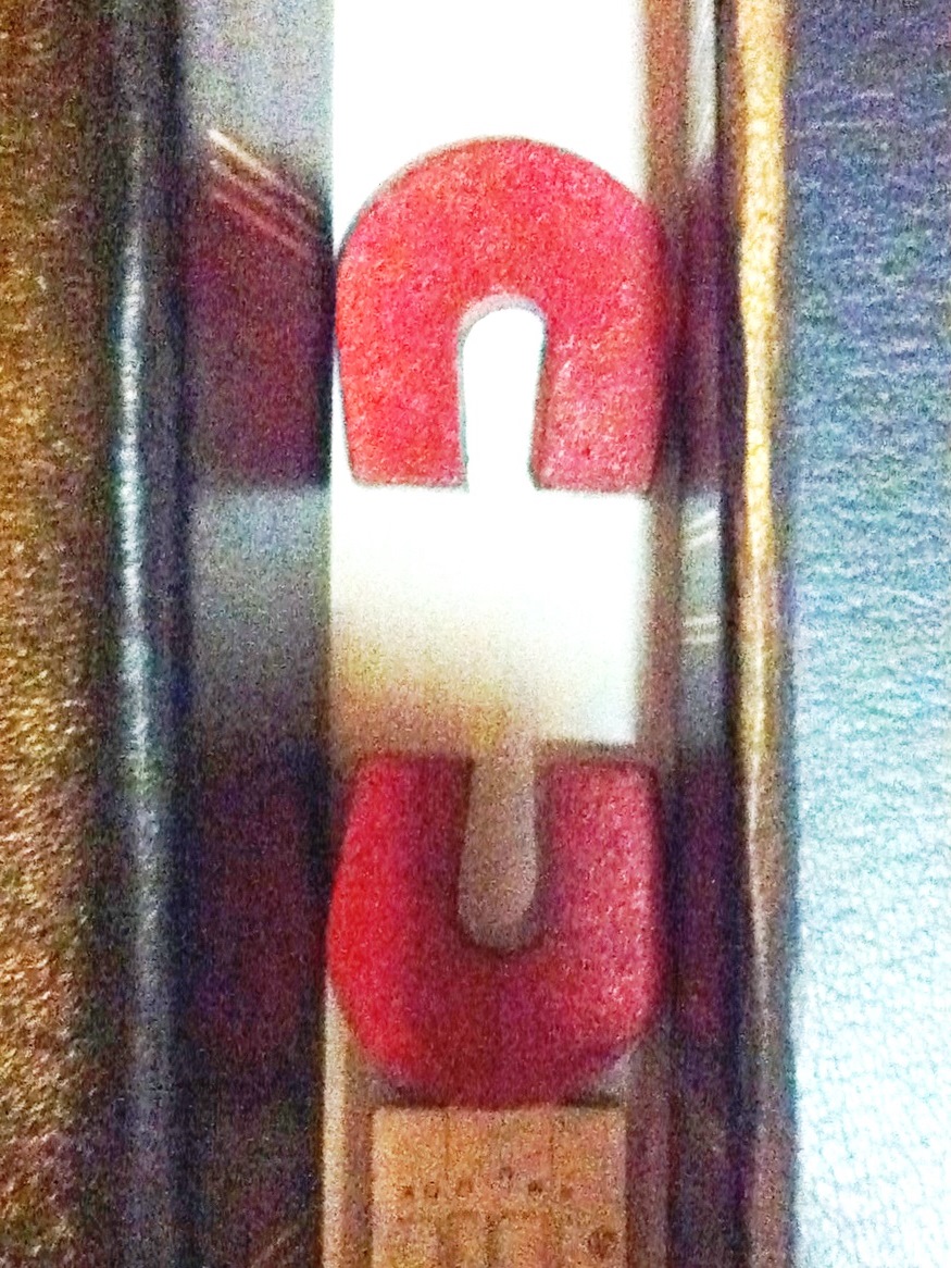
Magnets have two poles, labeled "North" and "South." The North poles attract South poles, while like poles repell each other. Click on the image of the horseshoe magnets to see a demonstration. The horseshoe magnets are permanent magnets, always having a magnetic field. Electromagnets, however, generate a magnetic field by circulating an electrical current through a coiled conductor. Click on the image of a coil to see a demonstration.
When the coiled conductor is a superconducting coil, it can support enormous currents, producing an extremely strong magnetic field. Further, if the coil forms a closed loop, the current will persist indefinitely, creating the equivalent of an extremely strong permanent magnet.
Linear Induction Motors/Generators
Electrical motors use a combination of permanent magnets and electromagnets to cause motion. Standard electrical motors are built in a circular fashion and cause the core to rotate. Linear induction motors string a set of electromagnets along a path, generating linear motion to an object by magnetic reaction.
In Sisyphus, the electromagnets are set into both sides of a concrete guideway. The Sisyphus vehicle has paired superconducting magnets that straddle the guideway. On each side of the guideway, the superconducting magnets consist of a superconducting magnet with its North end facing the guideway and another superconducting magnet with its South end facing the guideway. Click on the figure below for a demonstration and explanation.
Worked in reverse, the linear induction motor becomes a linear induction generator. If the vehicle is traveling (for example descending a slope under the force of gravity), it induces currents in the propulsion coils as it passes. This induction slows the vehicle converting the kinetic energy into an electrical current that is drawn off into the system output.
Induced Magnets
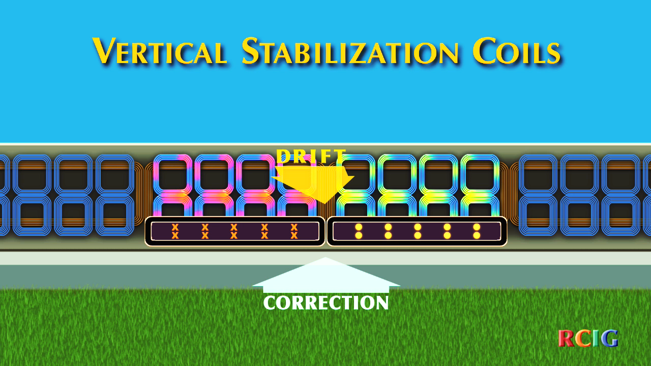
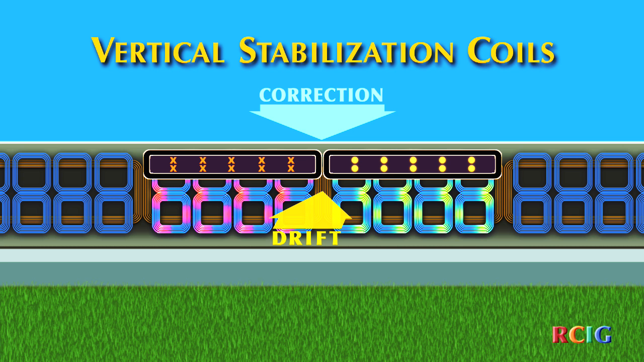
A moving magnetic field will induce currents in a conducting coil. The induced current creates an induced magnetic field, which repels the moving magnet. This reaction is used to automatically stabilize the Sisyphus vehicle. Click on each of the figures below for a demonstration and explanation.
Similarly, there are horizontal stabilization coils (not shown) on each side of the guideway. If the vehicle drifts right, it induces stronger currents in the coils on that side of the guideway, pushing the vehicle away from the guideway on that side. Likewise, if it drifts left, it is pushed away from that side. This automatically keeps the vehicle centered on the guideway.
Sisyphus Patents
James R. Powell and Gordon T. Danby created and patented a number of inventions in the field of superconducting magnetic levitation. Powell and Danby presented their original concepts in 1966 and received a patent in 1968. The original concept used low temperature superconducting (LTS) magnets (cooled with liquid helium). In 2000, they were awarded the Benjamin Franklin Medal in Engineering by the Franklin Institute for their work. Powell and Danby later improved their concept by using quadrupole superconducting magnets, rather than dipole magnets. The original quadrupole magnets are also LTS magnets; however, newer designs use high temperature superconducting (HTS) magnets (cooled with liquid nitrogen). Relevant patents for Sisyphus are listed in the table below.
| Patent Title | Patent # | Issue Date |
| Electromagnetic induction ground vehicle levitation guideway | 5511488, 5649489, 5809897 |
April 30, 1996 July 22, 1997 September 22, 1998 |
| Electromagnetic induction suspension and horizontal switching system for a vehicle on a planar guideway | 5503083, 5655458, 5669310, 5865123 |
April 2, 1996 August 12, 1997 September 23, 1997 February 2, 1999 |
| System and method for magnetic levitation guideway emplacement on conventional railroad lines installations | 5953996, 6085663 |
September 21, 1999 March 9, 2000 |
| Magnetic levitation system for long distance delivery of water | 6152045 | November 28, 2000 |
| Electric power storage and delivery using magnetic levitation technology | 7191710 | March 20, 2007 |
Applying the Science
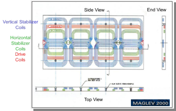
In the magnets section above, the electromagnets that provide motive power and generate electricity and the induced magnets that provide stabilization were described. The figure to the right is a schematic of the aluminum coils contained in the guideway panels.
- It shows four sets of paired coils colored blue. These are the vertical stabilizer coils. They act to raise the quadrupole (superconducting magnet on the vehicle, described below) unit if it drifts too low and to lower it if it drifts too high. This action is generated solely by the induced currents created by the quadrupole and does not require any external forces or actions (such as software controls). In addition to gross vehicle movement, these actions also automatically correct against tilting of the vehicle.
- The figure also shows four coils colored green. These coils are paired with the coils on the other side of the guideway and act to shift the quadrupoles (one on each side of the guideway) to the left or right to retain horizontal centering.
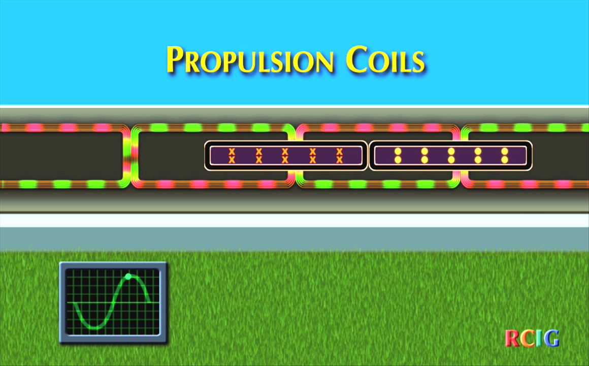
- Finally, the figure shows one coil colored red. This is the powered drive coil. Electronic switching connects it to
power only when the quadrupole is present. Adjoining panels are identical in construction; however, the current circulates
in the opposite direction. The power feed is a sinusoidal alternating current, so that the direction reverses during each cycle.
- In the motor mode, power is fed to the coil inducing the impulse to push the quadrupole in the desired direction. This is accomplished through the alternating current direction and the opposed circulations in the quadrupole.
- In the generator mode, power is drawn from the coil as the quadrupole moves past it. This slows the quadrupole, maintaining the desired speed, as the acceleration of gravity acts to increase the speed of the quadrupole. At the bottom of the hill, the quadrupole is stopped, drawing the last of the potential energy from the quadrupole, vehicle, and block.
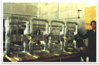
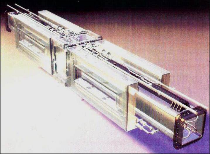
The photograph to the right shows a set of coils prior to being embedded in concrete.
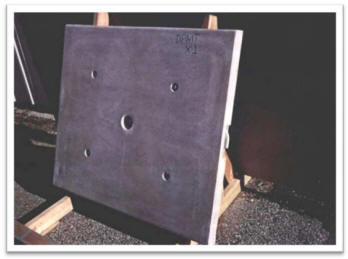
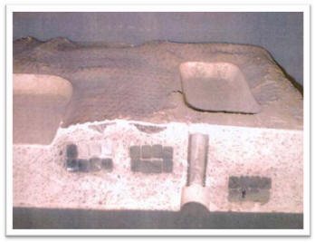
The left-hand photograph below shows half of a concrete panel containing the aluminum coils. The right-hand is a close up of the cross-section of the panel. In the photograph, cross-sections of three coils embedded in the concrete can be seen. The eight square aluminum conductors in each coil are visible: first on the left is part of a horizontal stabilizer coil, second is part of a drive coil, third is part of a vertical stabilizer coil.
The guideway acts as the non-contact track for the magnetically levitated vehicles of the Sisyphus system. Each side of the guideway has a set of panels attached that contain the aluminum coils that comprise the guideway half of the motor/generator system. The guideway is composed of a series of prefabricated beams. Each guideway beam is made of polymer concrete, which avoids the need for rebar strengthening. (Rebar would react magnetically to the moving superconducting magnets on the levitating vehicles.)
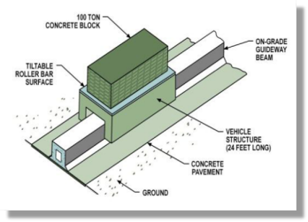
The figure to the right shows a perspective view of vehicle carrying a block on the guideway. The guideway is shown resting on grade; however, in certain applications, it could be mounted on pillars in the same fashion as the Disneyland Monorail.
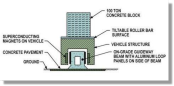
The figure to the right shows a cross-section of the vehicle and the guideway. This view shows the relationship of the superconducting magnets on the vehicle and the aluminum loop panels mounted on the sides of the guideway beam.
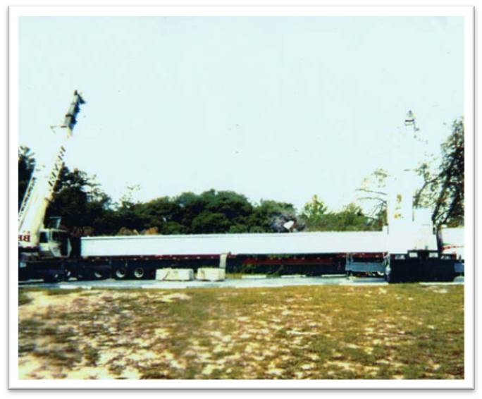
The figure below shows an actual section of guideway. In the picture, it is sitting on a semi-trailer (you can just make out three wheel sets at the left end, below the guideway beam. This and other photographs were taken during a $13 million test project performed in Florida.
The levitation/motor/generator system consists of two components, the superconducting quadrupole component and the non-superconducting aluminum coils. The quadrupole component contains four coils of superconducting wire that support an enormous lossless current. As long as the coils are maintained at the necessary low temperatures, these currents generate extremely strong magnetic fields. These fields interact with the aluminum coils, inducing currents and opposing magnetic fields. The magnetic fields play two roles: levitation and propulsion / power generation effects.
The interactions of these fields create the magnetic levitation effect, keeping the vehicle several centimeters above the guideway. The levitation may be supplemented by adding iron plates to the top of the guideway beam.
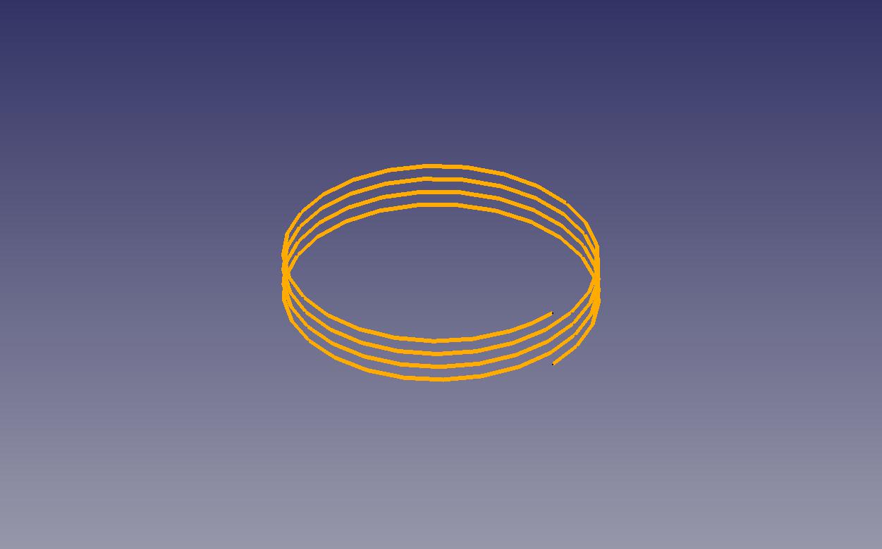
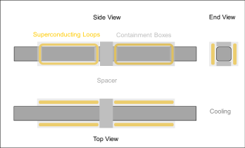
The figure to the right is a schematic of the quadrupole component, showing the superconducting coils as loops, the containment boxes that keep the loops in a superconducting state, and the cooling apparatus that maintains the temperature of the containment boxes. Looking at the side view, the two loops have currents circulating in opposite directions, so that the flow where the vertical parts are closest is in the same direction (up or down) for the two loops.
The figure to the right is a CAD/CAM perspective view of the quadrupole component, showing the four containment boxes.